


 30 / 48

Outdoor DIP Switches
General Installation
OUTDOOR UNIT
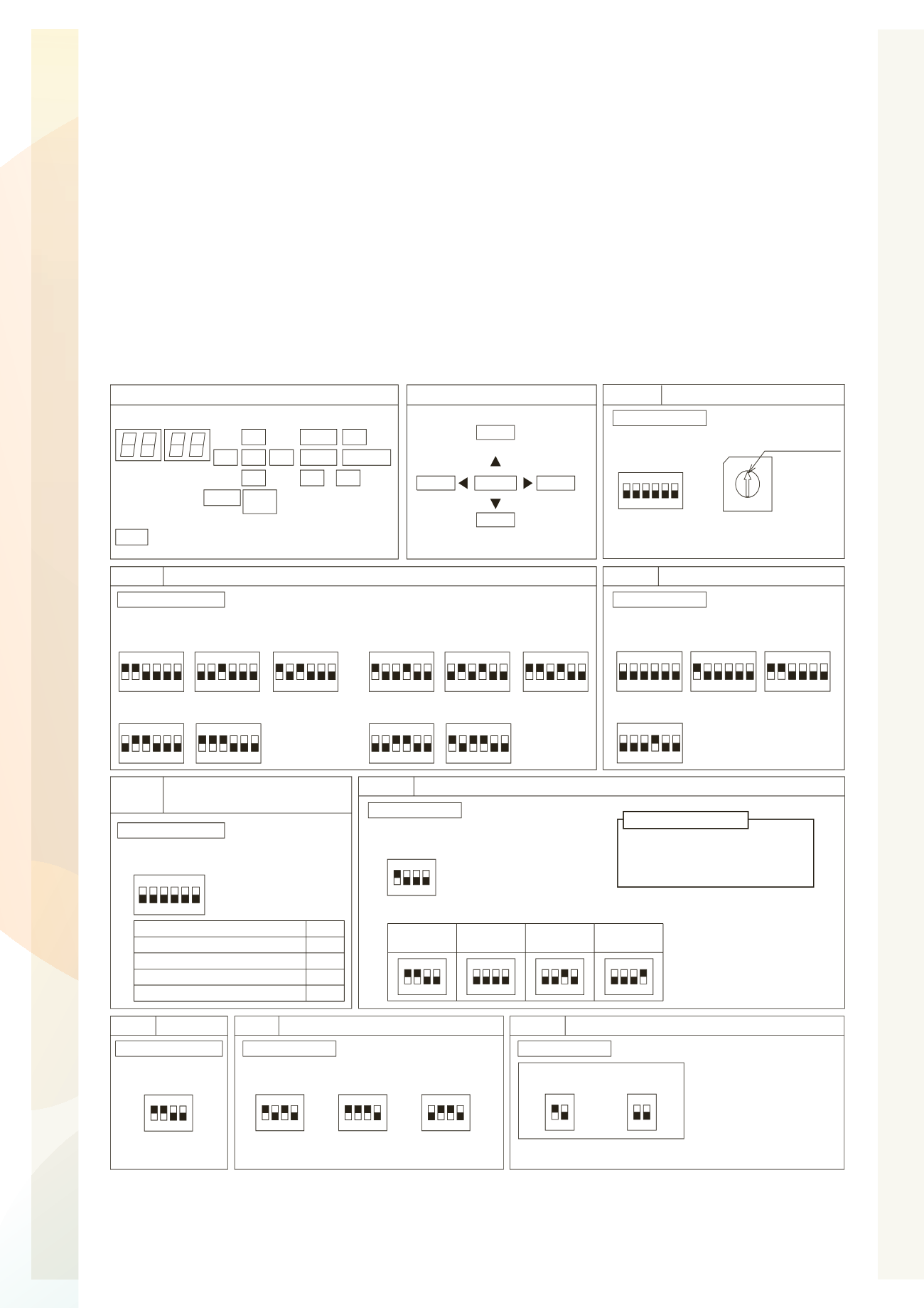
7.5 Dip Switch Setting of Outdoor Unit
TURN OFF all power sources before the setting.
Without turning OFF all power sources, the switches do not work and the setting are invalid.
(However, DSW4-No.1, 2, 4 and push switches can be operated while power source is ON.)
The mark “
Q
” indicates the position of dip switches. Set the dip switches according to the Fig.7.3.
O
By using switch DSW4, the unit is started 10 to 20 seconds after the switch
is operated.
O
For service and maintenance, number this outdoor unit to distinguish it
from the other outdoor units.
And write down the number in the box right.
NOTE
Fig. 7.3 DSW Setting
Ɣ
High Static Pressure Setting (DSW5-No.5: ON)
Turn ON DSW5-No.5 pin for the high static pressure setting.
This setting enables the high static pressure operation up to maximum of 60Pa.
NOTES:
Setting Item
Pin No.
Except No.1 Compressor Operation
Except No.2 Compressor Operation
Refrigerant Amount Judgement
1
2
4
High Static Pressure Mode
5
Turn ON the dip switch
when use the below
functions.
The outdoor unit is not single,
the combination setting is necessary.
Be sure to do this setting.
321
4
ON
5 6
DSW1
Tens Digit
0
7
9
5
8
6
4
3
Setting Position
1
2
RSW1
Last Digit
DSW1
Set the unit number of outdoor unit at each
refrigerant cycle. (Setting before shipment is unit 0.)
Ref. Cycle No. Setting
Setting Before Shipment
DSW10 Transmission Setting
For End Resistance Cancellation
End Resistance
Cancellation
21
ON
21
ON
Setting Before
Shipment
Test Operation and Service Setting
DSW4
For Test Operation and
Operating Compressor
1
ON
2 3 4 5 6
Setting Before
Shipment
Setting Before
Shipment
1
ON
2 3 4 5 6
Test Cooling
Operation
1
ON
2 3 4 5 6
Test Heating
Operation
1
ON
2 3 4 5 6
Compressor
Forced Stop
DSW5
321
4
ON
5 6
Emergency Operation/
Test Operation and Service Setting
21
ON
3 4
Single Setting
(Setting Before Shipment)
Capacity Setting
DSW2
1 3 4
ON
2
65
RAS-8FSXN1 RAS-10FSXN1 RAS-12FSXN1
RAS-14FSXN1 RAS-16FSXN1
1 3 4
ON
2
65
1 3 4
ON
2
65
1 3 4
ON
2
65
1 3 4
ON
2
65
1 3 4
ON
2
65
RAS-5FSXNH RAS-6FSXNH RAS-8FSXNH
RAS-10FSXNH RAS-12FSXNH
1 3 4
ON
2
65
1 3 4
ON
2
65
1 3 4
ON
2
65
1 3 4
ON
2
65
DSW7
ON
1
432
Arrangement of Dip Switch
SEG2
DSW6
DSW5
PSW3
SEG1
DSW4
DSW3
DSW2
PSW2
PSW1
DSW7
DSW10
PSW4
PSW5
DSW1 RSW1
Push Switches
PSW1
PSW2
PSW3
For
Checking
PSW5
For Checking
PSW4
For
Manual
Defrost
Enter
For Checking
DSW3
21
ON
3 4
Combination Setting (FSXN1: Unit A ~ D, FSXNH: Unit A ~ C)
21
ON
3 4
21
ON
3 4
Unit A
(No.0 Unit)
Unit B
(No.1 Unit)
Unit C
(No.2 Unit)
21
ON
3 4
Unit D
(No.3 Unit)
IMPORTANT NOTICE
Outdoor Unit No. Setting
DSW6
Setting is required.
Setting is required.
Setting is required.
No setting is required.
No setting is required.
Setting is required.
Setting is required.
21
ON
3 4
220V
21
ON
3 4
380V
21
ON
3 4
415V
Power Supply Setting
220V Unit: 220V Setting Before Shipment
380-415V Unit: 380V Setting Before Shipment
If the transmission circuit fuse is short circuited, the printed circuit board
PCB1 will be recovered only once by turning DSW10 #2 pin ON.
Set DSW10 #1 pin correctly in
the same H-LINK system.
Otherwise, it may cause abnormal
transmission.
No setting is required.