


 40 / 48

Interface Connection
All the interface connection are done with the PCC-1A
(CN3/CN7) connector (Part number 171000002).
Most commonly used / requested function are as below:- (external input / output)
1.
Remote start / stop operation
2.
Picking Up Operation Signal (External Fan Control / Fresh Air Fan)
3.
Picking Up AlarmSignal
1. Remote Start / Stop Operation. (level signal input)
Connect to CN3 pin 1&2.
OPTIONAL FUNCTION
(Indoor Unit)
4.1.3 Remote Control ON/OFF Function
This function rovides a co trol to stop and start the system from a remote place. Four methods are
available by using each signal from a building management system.
The factory-setting is as follows; “Remote Control 1” Signal Input to 1# and 2# of CN3 (item (1)), and
“Cancellation of Commands from Remote Control Switch after Forced Stoppage” Signal Input to 2# and 3#
of CN3. In case of using other functions, change the contact setting according to the item 4.1.1.
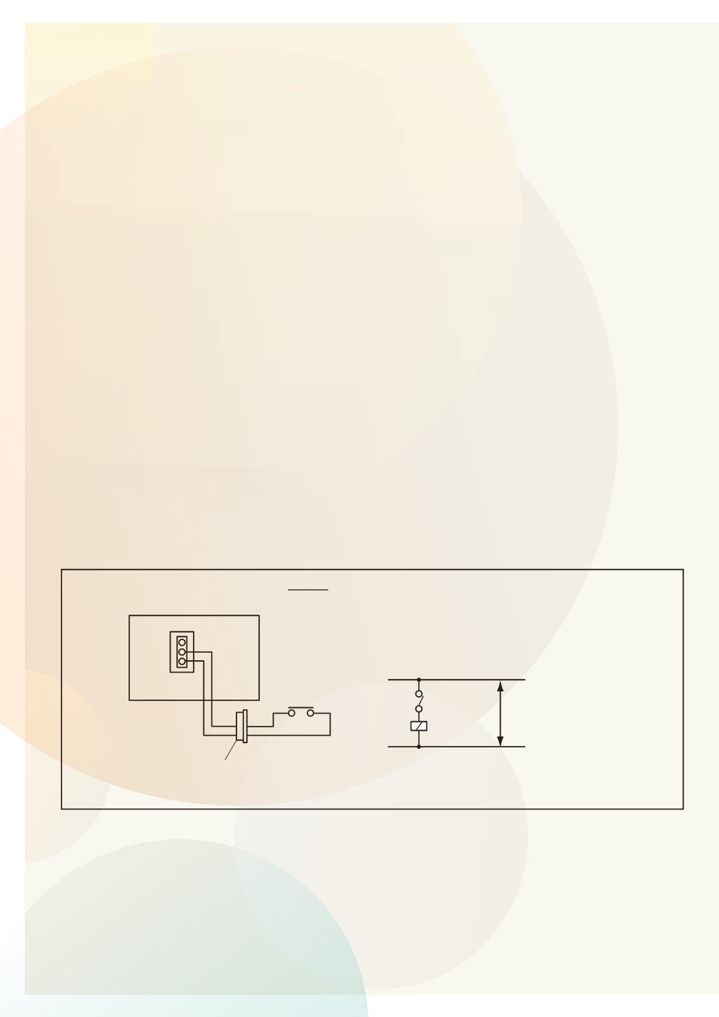
(1) Remote Control 1 (Level Signal Input)
This is an ON/OFF function from a remote place by using level signal (or ON/OFF). The basic wiring,
time chart are shown below.
(In Case of “Remote Control 1” Signal Input to 1# and 2# of CN3)
ON
OFF
ON
OFF
Time
Unit Operation
Signal to 1 & 2 of CN3
Control by R.C.S
Press the RUN/STOP switch.
NOTE:
Operation priority is given to the remote
ON/OFF signal or remote control switch
SS3
X1
Power
Source
Control Circuit
Indoor Unit PCB
CN3 (Example)
X1
3P Connector
2
1
2
1
NOTE:
When the unit is started by the remote ON/OFF switch,
the fan speed is subject to the mode memorized in
the remote control switch.
SS3: Remote Control ON/OFF
Wiring Diagram Example of Remote Control 1