


 45 / 48

Troubleshooting
Procedure :
4. Record the display from the outdoor 7 segment display and it’s parameter
Please follow the instruction on
the cover of the unit to navigate
the 7 segment parameters.
1-112
P5415179-rev.1
TROUBLESHOOTING
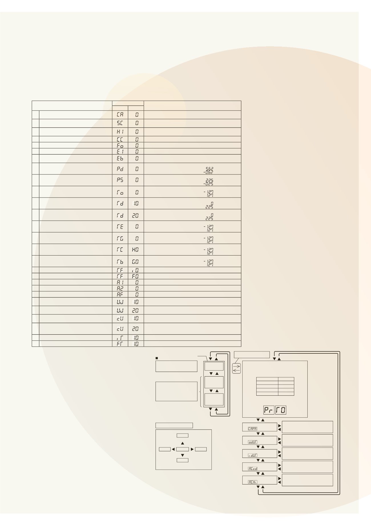
(C) Outdoor Unit Information
Select the outdoor combination unit No. for indication.
When the selection is changed, press PSW4 ( ) to forward or PSW2 ( ) to backward.
Select t e outdoor combination unit No. for indication by pressing PSW4 or PSW2.
Press PSW3( ) for details information.
Press PSW4( ) to forward or PSW2( ) to backward.
The information will be indicated alternately as “Item”
“Details”.
Press PSW5( ) for return to Outdoor Combination Unit No. Selection.
Unit
Indication
Unit A (No.0)
Unit B (No.1)
Unit C (No.2)
Unit D (No.3)
Item
7-Segment Display
Details
SEG2 SEG1
1 Outdoor Unit Capacity
*3)
Unit Capacity Indication
Refer to “Outdoor Unit Capacity Table”.
2 Output State of Outdoor Micro-Computer
Output State of Outdoor Micro-Computer Indication
Refer to “Location of Push Switches and 7-Segment Display”.
3 Running Frequency of
Inverter Compressor MC1
Running Frequency of INV. Compressor Indication
4 Total Number of Running Compressor
Total Number of Running Compressor Indication
5 Air Flow Rate
Air Flow Rate Indication (0 to 25 Steps)
6 Outdoor Expansion Valve MV1 Opening
Outdoor Expansion Valve MV1 Opening Indication (Unit: %)
7 Outdoor Unit Expansion Valve
MVB Opening for Bypass
Expansion Valve Opening for Bypass Indication (Unit: %)
8 Discharge Pressure (High)
Unit: MPa
Indication of Thermistor Open Circuit:
Indication of Thermistor Short Circuit:
9 Suction Pressure (Low)
Unit: MPa
Indication of Thermistor Open Circuit:
Indication of Thermistor Short Circuit:
10 Ambient Air Temperature (Ta)
Unit:
o
C
Indication of Thermistor Open Circuit:
Indication of Thermistor Short Circuit:
11 Discharge Gas Temperature
on the Top of Compressor MC1 (TD1)
Unit:
o
C
Indication of Thermistor Open Circuit:
Indication of Thermistor Short Circuit:
12 Discharge Gas Temperature
on the Top of Compressor MC2 (TD2)
Unit:
o
C (Only for 14, 16FSXN1)
Indication of Thermistor Open Circuit:
Indication of Thermistor Short Circuit:
13 Evaporating Temperature TE at Heating
Unit:
o
C
Indication of Thermistor Open Circuit:
Indication of Thermistor Short Circuit:
14 Outdoor Heat Exchanger Gas Temperature
Unit:
o
C
Indication of Thermistor Open Circuit:
Indication of Thermistor Short Circuit:
15 Supercooling Temperature
Unit:
o
C
Indication of Thermistor Open Circuit:
Indication of Thermistor Short Circuit:
16 Supercooling Temperature at Bypass
Unit:
o
C
Indication of Thermistor Open Circuit:
Indication of Thermistor Short Circuit:
17 Inverter Fin Temperature
Unit:
o
C
18 Fan Controller Fin Temperature
Unit:
o
C
19 Compressor MC1 Current
*1)
Unit: A
20 Compressor MC2 Current
*1)
Unit: A (Only for 14, 16FSXN1)
21 Fan Motor (MFO1) Current
*1)
Unit: A
22 Accumulated Operation Time of
Compressor MC1
Unit: Hour (Indication x 10Hours)
23 Accumulated Operation Time of
Compressor MC2
Unit: Hour (Indication x 10Hours)
(Only for 14, 16FSXN1)
24 Accumulated Operation Time of
Compressor MC1
Unit: Hour (Indication x 10Hours)
Accumulated operation time can be reset.
*2)
25 Accumulated Operation Time of
Compressor MC2
Unit: Hour (Indication x 10Hours)
(Only for 14, 16FSXN1)
Accumulated operation time can be reset.
*2)
26 Cause of Inverter Stoppage
Refer to “Inverter Stoppage Cause Table”.
27 Connected Indoor Unit Number
Refer to “Fan Controller Stoppage Cause Table”.
*1): The indicated current is reduced value. Use a clamp meter for the accurate current value.
*2): For resetting the accumulated operation time, press “PSW1 + PSW3” for 5 seconds while the accumulated data is
displayed.
*3): Th outdoor unit No. is ind cated on the one digit of “SEG1”.
(Example)
SEG2 SEG1
TROUBLESHOOTIN
To Start Checking
Push Switch Operation
Press PSW1 for once.
(A) Outdoor Combination Unit No.
Unit
Indication
PrT0
PrT1
PrT2
Unit A (No.0)
Unit B (No.1)
PrT3
Unit D (No.3)
Unit C (No.2)
Menu
To Cancel Checking Method
Press “PSW1” for more than 3 seconds while “Menu Mode” is displayed.
The indication of LCD will be turned off and condition will return to normal.
Make sure to cancel Checking Mode after checking is completed.
NOTICE
PSW1
PSW3
for Checking
for Checking
Enter
PSW5
PSW4
for Manual
Defrost
Connecting Information
Outdoor Unit Information
Indoor Unit Information
Cause of Alarm Code
History of Alarm Code
PSW2
for
Checking
The Details of indicated informations
shall be according to the (B)
“Connecting Information”.
The Details of indicated informations
shall be according to the (C)
“Outdoor Unit Information”.
The Details of indicated informations
shall be according to the (D)
“Indoor Unit Information”.
The Details of indicated informations
shall be according to the (E)
“Cause of Alarm Code Information”.
The Details of indicated informations
shall be according to the (F)
“Alarm Code History Information”.
Check Mode
“CHEC”
External
Input/Output
“ioST”
Function
Setting
“FUNC”
The outdoor combination unit No. is
indicated on the 7-segment display as follows.
Indication Example
Unit A (No.0)
Details of External
Input/Output Setting is shown
in item 4.2.
And Function Setting is shown
in item 4.3.
Press PSW1 for more than
3 seconds.
“Menu” will be indicated.
(5) Alarm Code
Refer to the item 1.2.1.
(6) Checking M th d by hecking Mode