


 43 / 48

Troubleshooting
Procedure :
2. Go to Check Mode 1 and record all the parameters
Shimizu Air Conditioning
Works,
No.
Hitachi Appliances, Inc.
SG201112A
Check 1
Sensor condition of air conditioner will be monitored and indicated.
Check 2
Sensor data of air conditioner prior to alarm occurrence will be indicated.
Alarm History Display
Previous alarm record (date, time, alarm code) will be indicated.
Model Display
Model name and manufacturing number will be indicated.
I.U./O.U. PCB Check
The result of PCB check will indicated.
Self Checking
Checking of remote control switch will be carried out.
●
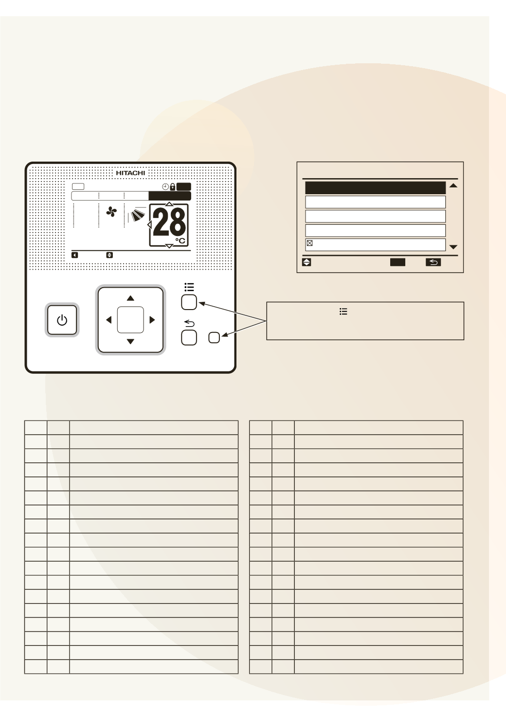
How to Display “Check Menu”
< Normal Mode Display >
< Check Menu Display >
A/C
COOL
HIGH
LOUV.
ADJ
Meeting Room
MODE SPEED LOUV.
TEMP
FLTR
OK
?
Check Menu
Function 5
Model Display
Alarm History Display
Check 2
01
/
02
Check 1
ENT.
RTN.
SEL.
OK
Press and hold “ ” (menu) and “?” (help)
simultaneously for at least 3 seconds during
the normal mode (when unit is not operated).
OPTIONAL FUNCTION
(Operation from Remote Control Switc
No. Item
Data Name
No. Item
Data Name
1 b1 Set Temp.
18 E3 Times of Abnormal Transmitting
2 b2 Inlet Air Temp.
19 E4 Times of Inverter Tripping
3 b3 Discharge Air Temp.
20 F1 Louver Sensor State
4 b4 Liquid Pipe Temp.
21 H1 Discharge Pressure
5 b5 Remote Thermistor Temp.
22 H2 Suction Pressure
6 b6 Outdoor Air Temp.
23 H3 Control Information
7 b7 Gas Pipe Temp.
24 H4 Operating Frequency
8 b8 Evaporating Temp. at Heating
25 J1 I.U. Capacity
9 b9 Condensing Temp. at Cooling
26 J2 O.U. Code
10 bA Comp. Top Temp.
27 J3 Refrigerant Cycle Number (1)
11 bb Thermo Temp. of Remote Control Switch 28 J4 Refrigerant Cycle Number (2)
12 bC Not Prepared
29 L1 I.U. Expansion Valve
13 C1 I.U. Micro-Computer
30 L2 O.U. Expansion Valve 1
14 C2 O.U. Micro-Computer
31 L3 O.U. Expansion Valve 2
15 d1 Stopping Cause State Indication
32 L4 O.U. Expansion Valve B
16 E1 Times of Abnormality
33 P1 Comp. Current
17 E2 Times of Power Failure
34 q1 Motion Sensor Reaction Rate (0 ~ 100%)
●
Items of Check Mode 1
●
Items of Check Mode 2
Page 43