


 42 / 48

Troubleshooting
Procedure :
1. Read and understand the Error Code from the wall controller (PC-ARF)
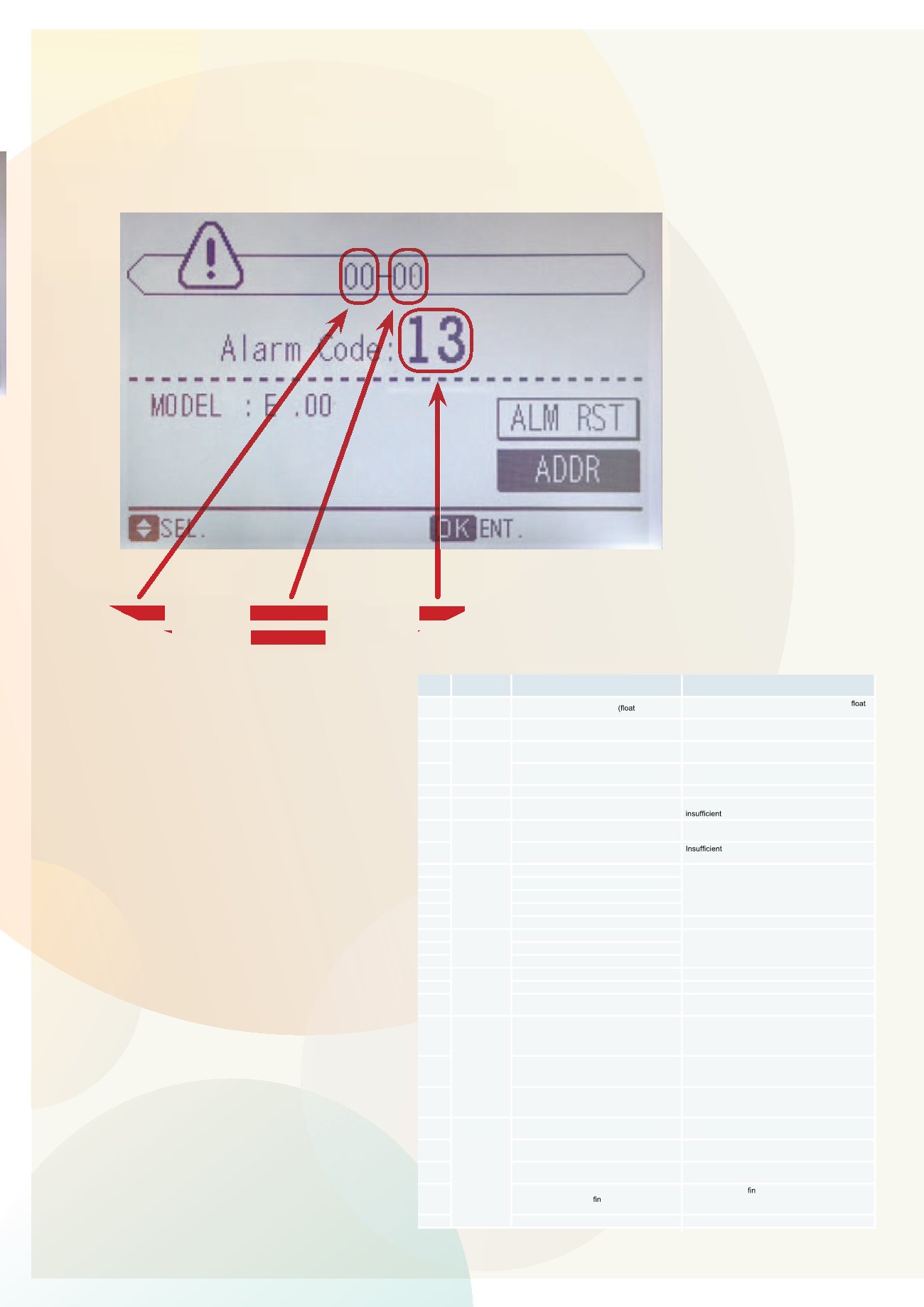
8.2.2 Alarm codes for the outdoor and indoor units
Code
number
Category
Type of abnormality
Main cause
01
Indoor unit
Activation of protection device switch)
Failure of fan motor, drain discharge, PCB, relay,
switch activated.
02
Outdoor unit
Activation of protection device
(high pressure cut)
Activation of PSH, locked motor, abnormal operation in
the power supply phase.
03
Transmission
Abnormality between indoor (or outdoor) and
outdoor (or indoor) units
Incorrect wiring. Loose terminals, Failure of PCB.
Tripping of fuse. Power supply OFF.
04
Abnormal operation between IPM and
control PCB
Transmission failure between PCBs
05 Power supply Abnormal power supply
Power source with abnormal wave pattern.
06
Voltage drop Voltage drop due to excessively low or high
voltage in outdoor unit
Voltage drop in power supply. Incorrect wiring or
capacity of power supply wiring.
07
Cycle
Drop in discharge gas overheating
Excessive refrigerant charge. Expansion valve lock
open.
08
Increase in discharge gas temperature
refrigerant charge, refrigerant leakage.
Expansion valve closed or clogged.
11
Sensor in
indoor unit
Inlet air thermistor
Failure of thermistor, sensor, connection.
12
Outlet air thermistor
13
Anti-freeze thermistor
14
Gas pipe thermistor
19
Protection device for fan motor is triggered
Failure of fan motor
20
Outdoor unit
sensor
Compressor thermistor
Failure of thermistor, sensor, connection.
22
Outside air thermistor
24
Evaporation thermistor
31
System
Incorrect setting of outdoor and indoor units
Incorrect setting of capacity code.
35
Incorrect setting of indoor unit number
Duplication of indoor unit number.
38
Abnormality of protective circuit in outdoor unit
Failure of indoor unit PCB; incorrect wiring; connection
to indoor unit PCB.
41
Pressure
Cooling overload (possible activation of high
pressure device)
OU pipe thermistor temperature is higher than 55 ºC
and the compressor top temperature is higher than
95 ºC, OU
protection device is activated.
42
Heating overload (high-pressure device may be
activated)
If IU freeze protection thermistor temperature is higher
than 55 ºC and compressor top temperature is higher
than 95 ºC, OU protection device is activated.
47
Activation of protection device for low pressure
drop
Stoppage due to excessive decrease of evaporating
temperature (Temperature < -35 ºC) is activated 3
times in one hour, motor locked in heating mode.
48
Inverter
Activation of overcurrent protection
Overload, overcurrent. Failure of IPM, heat exchanger
clogged, locked compressor.
51
Abnormality in inverter current sensor
Incorrect wiring of current sensor. Failure of control
PCB or IPM.
53
Activation of transistor module protection device Abnormality of IPM.
Compressor failure, heat exchanger clogged.
54
Abnormality of inverter temperature
Abnormal inverter thermistor.
Heat exchanger clogged.
Abnormal outdoor fan.
55
Abnormality of inverter module
Failure of IPM.
8. Troubleshooting
Indoor
Address
Outdoor
Address
Error
Code